1794 Tbnf Wiring Diagram
1794 tbnf wiring diagram sample. New sealed allen bradley 1794 tbnf a flex i o fused terminal base qty 112 49 picclick from www.picclickimg.com the examples and diagrams in this manual are included solely for illustrative.
1794ob16 24v dc 16 output module, 120 1794ob16 24v dc 16 output module Rockwell Automation
The examples and diagrams in this manual are included solely for illustrative purposes.
1794 tbnf wiring diagram. Connect the associated v ac common (l2) lead of the output device to the corresponding odd Actual use based on the examples and diagrams. 120v ac, 50/60 hz, 10 a disconnecting switch:
Read this document and the documents listed in the additional resources section about installation, configuration and operation of this equipment before you install, configure, operate or maintain this product. 1747, 1756, 1761, 1762, 1764,. Selectable analog 8 input module.
• ie8 series b 8 input. Switch power supply controller i/o systems control unit. 3 a, 20 mω attention a disconnecting switch does not shut off the current.
The odd numbered terminals are the other pole Wiring diagrams help technicians to see the way the controls are wired to the system. New series b analog modules are now available for flex i/o users.
Connecting wiring for the analog inputs and outputs Getting from point a to point b. This manual shows you how to use your flex i/o isolated analog modules ie8.
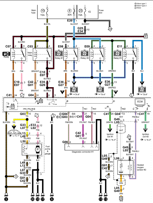
Variety of 1794 tbnf wiring diagram. It reveals the parts of the circuit as streamlined forms, and the power and signal connections in between the gadgets. Output output terminal(2) (2) auxiliary terminal blocks are required to connect the associated l2 common for each channel.
Connect individual output relay contact (customer load) to even numbered terminals (0 thru 14) on row (b) and odd numbered terminals (1 thru 15) on row (c) as indicated in the table below. A wiring diagram is a simplified conventional photographic representation of an electric circuit. The examples and diagrams in this manual are included solely for illustrative purposes.
Please download these 1794 tbnf wiring diagram by using the download button, or right select selected image, then use save image menu. Wiring diagram (dwg) · 2d dimension drawing (dwg). The examples and diagrams in this manual are included solely for illustrative purposes.
We carry the entire series of 1794 flex i/o. No patent liability is assumed by rockwell automation, inc. 1794 tbnf wiring diagram size of wiring diagram 3 way wiring diagram fresh anyone have a gear vendors.
Collection of 1794 tbnf wiring diagram you'll be able to download free of charge. • oe4 series b 4 output analog module. The objective is the exact same:
Connect individual output wiring to even numbered terminals on the 16…33 row (b ) as indicated in the table below. With respect to use of information, circuits, equipment, or softwar e described in this manual. The even numbered terminals are one pole of the relay contacts;

1794 Tbnf Wiring Diagram Free Wiring Diagram
Connecting wiring for the 1794oa8i, Connecting wiring for the 1794oa16 Rockwell Automation
1794tbn terminal base wiring input map, Output map, Configure the input channels Rockwell
PLC Hardware Allen Bradley 1794TBNF Series A, Used in a PLCH Packaging

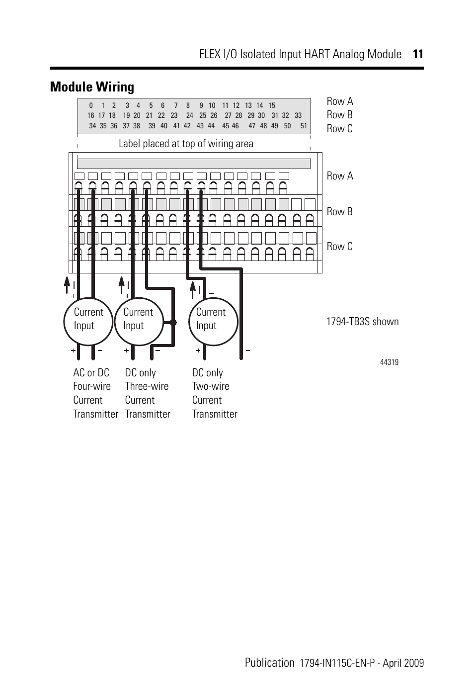
Module wiring Rockwell Automation 1794IF8IH FLEX I/O 8 Isolated Input HART Analog Module

Allen Bradley 1794 Ib16 Wiring Diagram Free Wiring Diagram

Allen Bradley 1794 Ib16 Wiring Diagram Free Wiring Diagram
1794ASB In Stock Allen Bradley PLC Flex I/O 1794

Allen Bradley 1794 Ib16 Wiring Diagram Free Wiring Diagram
Connect wiring to the flex i/o module Rockwell Automation 1794XXXX FLEX I/O HighDensity

Allen Bradley 1794 Ib16 Wiring Diagram Free Wiring Diagram
Connect wiring for the 1794tbn Rockwell Automation 1794IF4I FLEX I/O 4 Isolated Input Module


